Treatment Plant
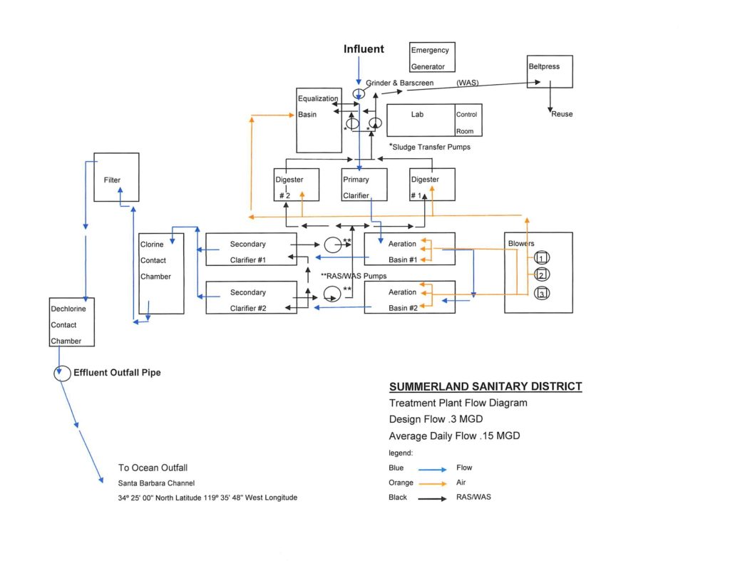
Flow Diagram -click on for the treatment plant flow diagram to enlarge –
The treatment process provides optimal conditions for natural degradation of pollutants in the wastewater. A high quality, disinfected effluent treated to tertiary standards is produced that consistently exceeds state and national standards for ocean discharge. The plant is staffed by licensed operators with maintenance and mechanical skills.
The treatment plant operation consists of:
- A grinder at the headworks
- A flow equalization basin
- One primary clarifier
- Two aerobic digesters
- Two activated sludge aeration basins
- Two secondary clarifiers
- One chlorine contact chamber
- One anthracite filter
- One de-chlorination chamber
- And an 740 ft. ocean outfall
Collection System
The District maintains more than eight miles of sewer lines ranging from six inches to twelve inches in diameter. There are approximately 150 manholes and cleanouts within the system; these are used for access points for cleaning and inspection purposes.
An important part of the District responsibilities is systematic cleaning and closed circuit televising (CCTV) of the collection system to identify problem areas and see firsthand the effectiveness of cleaning efforts. Cleaning and CCTV maintenance is primarily done by District staff. A small portion consisting of the large diameter pipelines are contracted out.
There are three wastewater pump stations located within the collection system that are necessary to convey flow to the wastewater treatment plant. These pump stations have redundant pumping equipment and emergency standby generators that are designed to handle wet weather flow rates.


